Product Description
Product Description
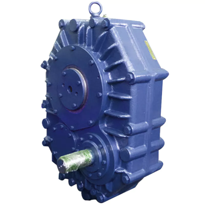
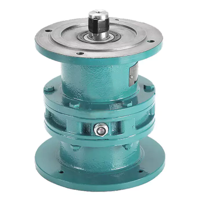
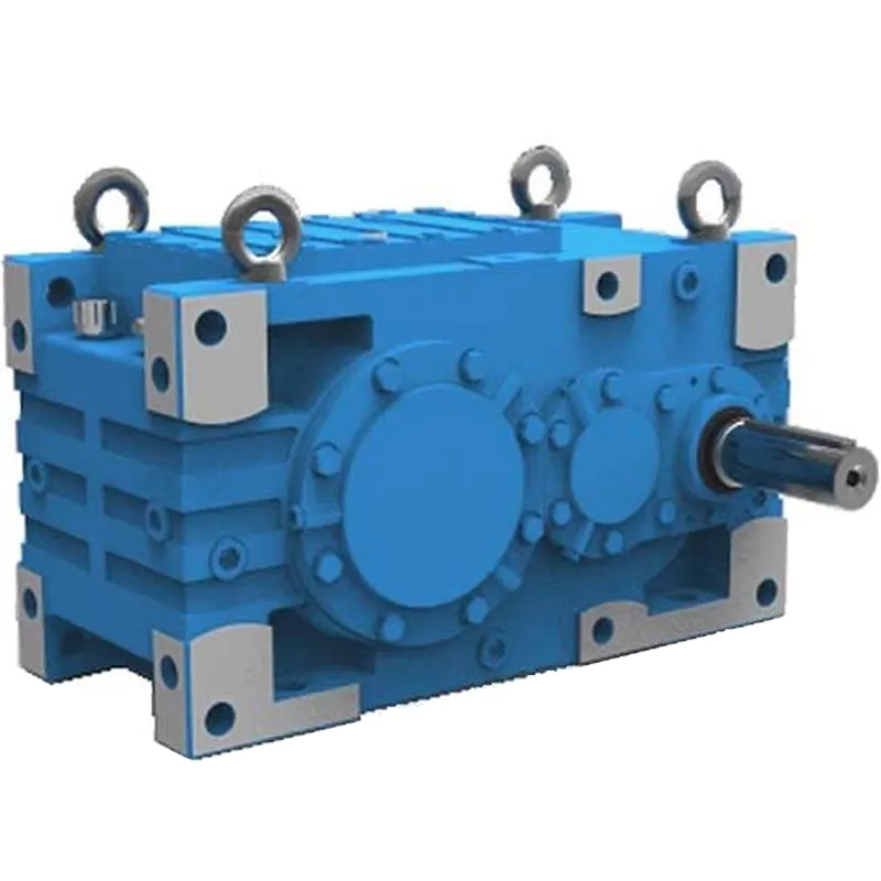
ATA Series Shaft mounted Gearbox Reducer SMR Series Shaft mounted Gearbox Reducer
ATA series shaft mounted gearbox(speed reducer) with helical hardened gears has the characteristics of high carrying capacity, smooth transmission, light weight, low energy consumption and so on. Input shaft of ATA speed reducer is connected with gear motor by belt pulley, hollow output shaft is linked with a key. It can be replaced by electric drum as power for belt conveyors and lifting equipments. ATA series shaft mounted gearbox could be attached with back-stop to avoid the working machine back skating, and conveniently mounted by tie rod. ATA series shaft mounted speed reducer is widely applied in the mining equipments, concrete mixing batching plant, stone crushers, sand making production line and other belt conveyors, mechanical transmission areas.
Mechanical belt conveyors drive system is composed of ATA shaft mounted speed reducer, torque arm, pulleys and gear motors, whose power transmission from the gear motor to the gearbox through the pulley, and then speed reducer passed to the drive pulley through the hollow output shaft and the gearbox is fixed by torque arm, anti-slip device can be configured. The system is convenient to install,use and maintain.
Features
Mounting Type: Tie rod Hanging shaft mounted
Output Shaft: Single key hollow shaft, each model can select 3 hollow diameter at most.
Gearbox Housing: Hard Iron Steel, can be used outside.
Anti-slip device: Can suit for any model, It’s very convenient to be mounted.
Application
Stone crushers plant , Cement plant, Concrete batch mixing plant, Mining conveyors, Port transfer
conveyor, Crushing machine, etc ···
Characteristic
1) All gears are heat treated and fixed to achieve low noise and high output
2) Mounting dimensions are interchangeable with Fenner
Product Parameters
| TA Shaft Mounted Reducer | Output Shaft Bore [mm] | Ratio(i) | Rated torque | |
| TA30 | Φ30 | 7, 10, 12.5 | 180N.m | |
| TA35 | Φ35 | 5,10,15,20,25 | 420N.m | |
| TA40 | Φ40 | 5,10,12.5,15,20,25 | 900N.m | |
| Φ45 | ||||
| TA45 | Φ45 | 5,10,12.5,15,20,25 | 1400N.m | |
| Φ50 | ||||
| Φ55 | ||||
| TA50 | Φ50 | 5,10,12.5,15,20,25 | 2300N.m | |
| Φ55 | ||||
| Φ60 | ||||
| TA60 | Φ60 | 5,10,12.5,15,20,25 | 3600N.m | |
| Φ70 | ||||
| TA70 | Φ70 | 5,10,12.5,15,20,25,31 | 5100N.m | |
| Φ85 | ||||
| TA80 | Φ80 | 5,10,12.5,15,20,25,31 | 7000N.m | |
| Φ100 | ||||
| TA100 | Φ100 | 5,10,12.5,15,20,25,31 | 11000N.m | |
| SMR Model No. |
Output Shaft Bore [mm] |
Ratio(i) | ||
| Standard | Alternative | 5:1 13:1 20:1 |
||
| B | Φ30 | Φ40 | ||
| C | Φ40 | Φ50 | ||
| D | Φ50 | Φ55 | ||
| E | Φ55 | Φ65 | ||
| F | Φ65 | Φ75 | ||
| G | Φ75 | Φ85 | ||
| H | Φ85 | Φ100 | ||
| J | Φ100 | Φ120 | ||
Production Process
/* January 22, 2571 19:08:37 */!function(){function s(e,r){var a,o={};try{e&&e.split(“,”).forEach(function(e,t){e&&(a=e.match(/(.*?):(.*)$/))&&1
| Application: | Motor, Industry Conveyor |
|---|---|
| Function: | Distribution Power, Speed Changing |
| Layout: | Cycloidal |
| Hardness: | Hardened Tooth Surface |
| Installation: | Torque Arm Type |
| Step: | Stepless |
| Customization: |
Available
| Customized Request |
|---|

Are there any disadvantages or limitations to using gear reducer systems?
While gear reducer systems offer numerous advantages, they also come with certain disadvantages and limitations that should be considered during the selection and implementation process:
1. Size and Weight: Gear reducers can be bulky and heavy, especially for applications requiring high gear ratios. This can impact the overall size and weight of the machinery or equipment, which may be a concern in space-constrained environments.
2. Efficiency Loss: Despite their high efficiency, gear reducers can experience energy losses due to friction between gear teeth and other components. This can lead to a reduction in overall system efficiency, particularly in cases where multiple gear stages are used.
3. Cost: The design, manufacturing, and assembly of gear reducers can involve complex processes and precision machining, which can contribute to higher initial costs compared to other power transmission solutions.
4. Maintenance: Gear reducer systems require regular maintenance, including lubrication, inspection, and potential gear replacement over time. Maintenance activities can lead to downtime and associated costs in industrial settings.
5. Noise and Vibration: Gear reducers can generate noise and vibrations, especially at high speeds or when operating under heavy loads. Additional measures may be needed to mitigate noise and vibration issues.
6. Limited Gear Ratios: While gear reducers offer a wide range of gear ratios, there may be limitations in achieving extremely high or low ratios in certain designs.
7. Temperature Sensitivity: Extreme temperatures can affect the performance of gear reducer systems, particularly if inadequate lubrication or cooling is provided.
8. Shock Loads: While gear reducers are designed to handle shock loads to some extent, severe shock loads or abrupt changes in torque can still lead to potential damage or premature wear.
Despite these limitations, gear reducer systems remain widely used and versatile components in various industries, and their disadvantages can often be mitigated through proper design, selection, and maintenance practices.

How do gear reducers handle shock loads and sudden changes in torque?
Gear reducers are designed to handle shock loads and sudden changes in torque through several mechanisms that enhance their durability and reliability in challenging operating conditions.
1. Robust Construction: Gear reducers are constructed using high-strength materials and precision manufacturing techniques. This ensures that the gears, bearings, and other components can withstand sudden impacts and high torque fluctuations without deformation or failure.
2. Shock-Absorbing Features: Some gear reducer designs incorporate shock-absorbing features, such as flexible couplings, elastomeric elements, or torsionally flexible gear designs. These features help dampen and dissipate the energy from sudden shocks or torque spikes, reducing the impact on the entire system.
3. Torque Limiters: In applications where shock loads are common, torque limiters may be integrated into the gear reducer. These devices automatically disengage or slip when a certain torque threshold is exceeded, preventing damage to the gears and other components.
4. Overload Protection: Gear reducers can be equipped with overload protection mechanisms, such as shear pins or torque sensors. These mechanisms detect excessive torque and disengage the drive temporarily, allowing the system to absorb the shock or adjust to the sudden torque change.
5. Proper Lubrication: Adequate lubrication is essential for managing shock loads and sudden torque changes. High-quality lubricants reduce friction and wear, helping the gear reducer withstand dynamic forces and maintain smooth operation.
6. Dynamic Load Distribution: Gear reducers distribute dynamic loads across multiple gear teeth, which helps prevent localized stress concentrations. This feature minimizes the risk of tooth breakage and gear damage when subjected to sudden changes in torque.
By incorporating these design features and mechanisms, gear reducers can effectively handle shock loads and sudden changes in torque, ensuring the longevity and reliability of various industrial and mechanical systems.

Can you explain the different types of gear reducers available in the market?
There are several types of gear reducers commonly used in industrial applications:
1. Spur Gear Reducers: These reducers have straight teeth and are cost-effective for applications requiring moderate torque and speed reduction. They are efficient but may produce more noise compared to other types.
2. Helical Gear Reducers: Helical gears have angled teeth, which provide smoother and quieter operation compared to spur gears. They offer higher torque capacities and are suitable for heavy-duty applications.
3. Bevel Gear Reducers: Bevel gears have conical shapes and intersect at an angle, allowing them to transmit power between non-parallel shafts. They are commonly used in applications where shafts intersect at 90 degrees.
4. Worm Gear Reducers: Worm gears consist of a worm (screw) and a mating gear (worm wheel). They offer high torque reduction and are used for applications requiring high ratios, although they can be less efficient.
5. Planetary Gear Reducers: These reducers use a system of planetary gears to achieve high torque output in a compact design. They provide excellent torque multiplication and are commonly used in robotics and automation.
6. Cycloidal Gear Reducers: Cycloidal drives use an eccentric cam to achieve speed reduction. They offer high shock load resistance and are suitable for applications with frequent starting and stopping.
7. Harmonic Drive Reducers: Harmonic drives use a flexible spline to achieve high gear reduction ratios. They provide high precision and are commonly used in applications requiring accurate positioning.
8. Hypoid Gear Reducers: Hypoid gears have helical teeth and non-intersecting shafts, making them suitable for applications with space limitations. They offer high torque and efficiency.
Each type of gear reducer has its own advantages and limitations, and the choice depends on factors such as torque requirements, speed ratios, noise levels, space constraints, and application-specific needs.


editor by CX 2024-04-16
by
Tags:
Leave a Reply