Product Description
Product Description
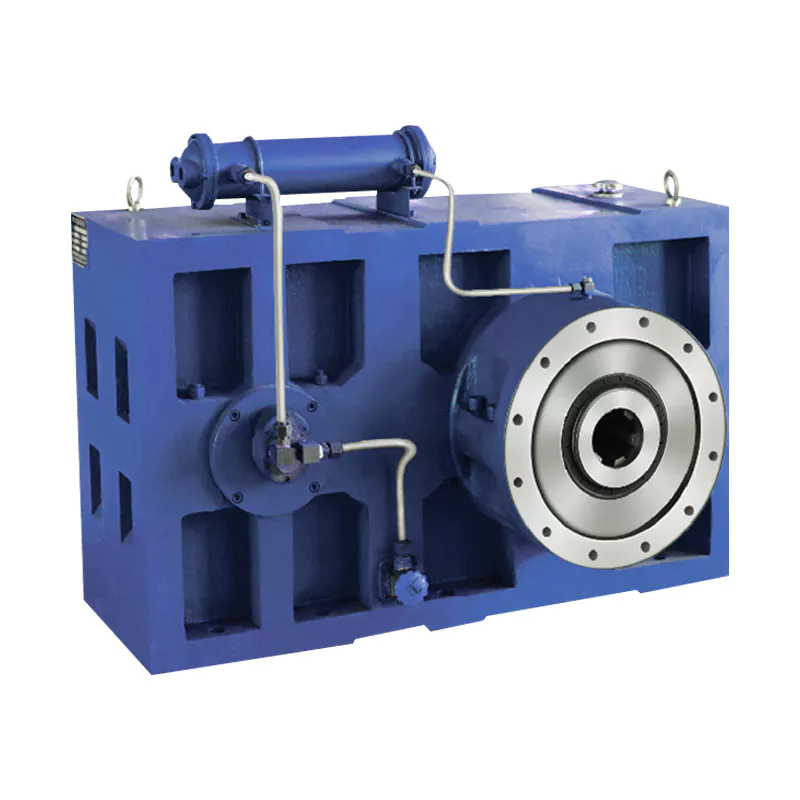
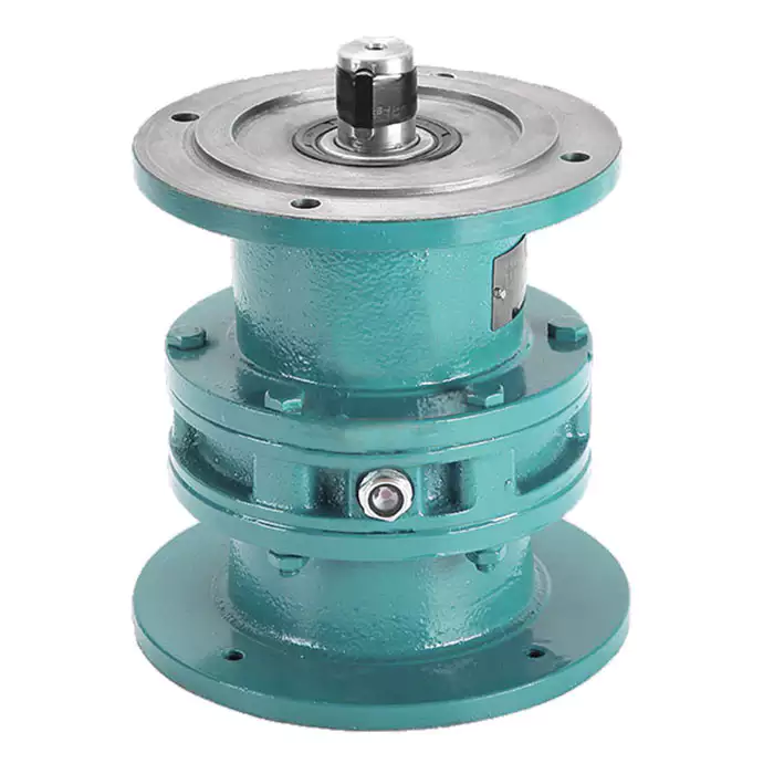
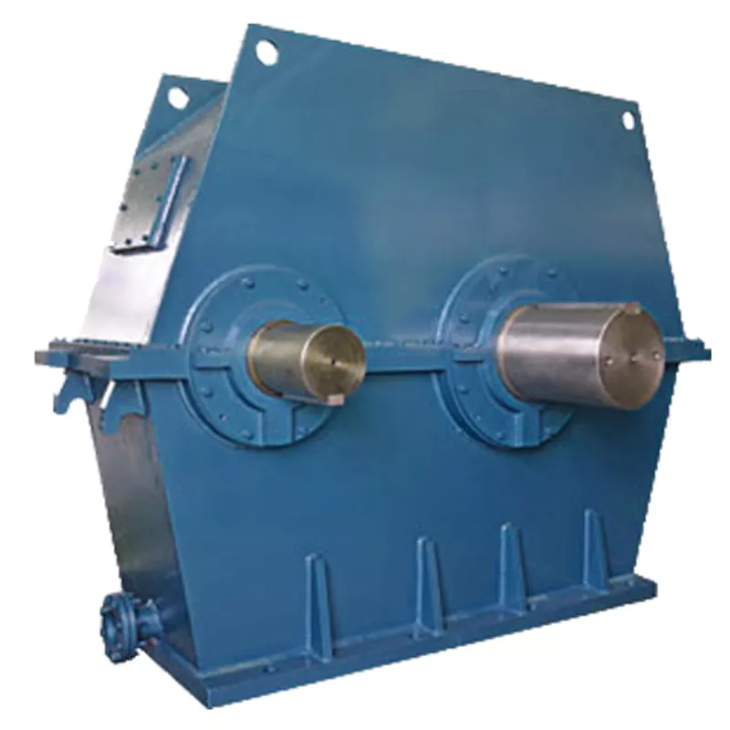
High torque foot mounted customized casting iron hypoid gear reducer
1.KM series Helical-hypoid Gearbox’s Characteristics
KM series helical-hypoid gearbox is a new-generation of product developed by Aokman. With a compromise of advanced technology both at home and abroad, its main features are as follows:
(1) Driven by hypoid gears, which has big ratios.
(2) Large output torque, high efficiency, energy saving and environmental protection.
(3) High-quality aluminum alloy housing, and light in weight and non-rusting.
(4) Smooth in running and low in noise, and can work long time in dreadful conditions.
(5) Good-looking in appearance, durable in service life and small in volume.
(6) Suitable for all round installation, wide application and easy use.
(7) The mounting dimension of KM series helical-hypoid gearbox are compatible with RV series worm gearbox.
(8) Modular and multi-structure can meet the demands of various conditions.
Detailed Photos
2. KM series Helical-hypoid Gearbox’s Main Materials
(1) Housing: die-cast aluminum alloy (frame size 27 to 57)
(2) Gear wheel: 20CrMnTiH1 carbonizing & quenching heat treatment make the hardness of gears surface be up to 56-62 HRC, and be retained carburization layers thickness between 0.3 and 0.5mm after precise grinding.
3. KM series Helical-hypoid Gearbox’s Surface Painting
Aluminum alloy housing:
(1) Shot blasting and special antiseptic treatment on the aluminum alloy surface.
(2) After phosphating, spray the RAL9571 silver white paint.4.Gearbox Parameters
Product Parameters
| Models | Stage | Nominal Ratio | Output Speed (n2)* | Max. Torque | Input Shaft Dia. | Output Hole Dia. | Output Shaft Dia. |
| KM050 | 3 Stage | 50~300 | 4.8~27 | 130N.m | Φ11 | Φ20, Φ24 | Φ25 |
| 2 Stage | 7.5~60 | 24~181 | 130N.m | Φ11 | |||
| KM063 | 3 Stage | 50~300 | 4.6~27 | 200N.m | Φ11 | Φ25, Φ28 | Φ25 |
| 2 Stage | 7.5~60 | 23~184 | 200N.m | Φ14 | |||
| KM075 | 3 Stage | 50~300 | 4.7~28 | 350N.m | Φ14 | Φ28, Φ30, Φ35 | Φ28 |
| 2 Stage | 7.5~60 | 24~187 | 350N.m | Φ16 | |||
| KM090 | 3 Stage | 50~300 | 4.7~28 | 500N.m | Φ14 | Φ35, Φ38 | Φ35 |
| 2 Stage | 7.5~60 | 24~187 | 500N.m | Φ19 | |||
| KM110 | 3 Stage | 50~300 | 4.7~27 | 750N.m | Φ19 | Φ40, Φ42 | Φ42 |
| 2 Stage | 7.5~60 | 24~187 | 750N.m | Φ24 |
Packaging & Shipping
Company Profile
Our Advantages
After Sales Service
| Pre-sale services | 1. Select equipment model. |
| 2.Design and manufacture products according to clients’ special requirement. | |
| 3.Train technical personal for clients | |
| Services during selling | 1.Pre-check and accept products ahead of delivery. |
| 2. Help clients to draft solving plans. | |
| After-sale services | 1.Assist clients to prepare for the first construction scheme. |
| 2. Train the first-line operators. | |
| 3.Take initiative to eliminate the trouble rapidly. | |
| 4. Provide technical exchanging. |
FAQ
1.Q:What kinds of gearbox can you produce for us?
A:Main products of our company: UDL series speed variator,RV series worm gear reducer, ATA series shaft mounted gearbox, X,B series gear reducer,
P series planetary gearbox and R, S, K, and F series helical-tooth reducer, more
than 1 hundred models and thousands of specifications
2.Q:Can you make as per custom drawing?
A: Yes, we offer customized service for customers.
3.Q:What is your terms of payment ?
A: 30% Advance payment by T/T after signing the contract.70% before delivery
4.Q:What is your MOQ?
A: 1 Set
If you have any demand for our products please feel free to contact me. /* January 22, 2571 19:08:37 */!function(){function s(e,r){var a,o={};try{e&&e.split(“,”).forEach(function(e,t){e&&(a=e.match(/(.*?):(.*)$/))&&1
| Application: | Motor, Machinery |
|---|---|
| Function: | Speed Changing, Speed Reduction |
| Layout: | Orthogonal |
| Hardness: | Hardened Tooth Surface |
| Installation: | Industry |
| Step: | Double or Three-Step |
| Customization: |
Available
| Customized Request |
|---|

Can you provide real-world examples of products that use gear reducer technology?
Certainly! Gear reducer technology is widely used in various industries and products to enhance performance and efficiency. Here are some real-world examples:
1. Industrial Machinery: Gear reducers are commonly used in manufacturing machinery, such as conveyor systems, material handling equipment, and assembly lines, where they help control speed and torque for precise operations.
2. Wind Turbines: Wind turbines utilize gear reducers to transform the low rotational speed of the wind turbine rotor into the higher speed needed for electricity generation, optimizing energy conversion.
3. Automotive Transmissions: Automobiles use gear reducers as part of their transmissions to optimize power delivery from the engine to the wheels, allowing the vehicle to operate efficiently at different speeds.
4. Robotics: Robotic systems rely on gear reducers to control the movement and articulation of robot arms, enabling precise and controlled motion for various applications.
5. Printing Presses: Gear reducers are integral to printing presses, ensuring accurate and synchronized movement of printing plates, rollers, and paper feed mechanisms.
6. Conveyor Belts: Conveyor systems in industries like mining, agriculture, and logistics use gear reducers to regulate the movement of materials along the conveyor belts.
7. Packaging Machinery: Gear reducers play a crucial role in packaging machines, controlling the speed and movement of packaging materials, filling mechanisms, and sealing components.
8. Cranes and Hoists: Cranes and hoists rely on gear reducers to lift heavy loads with precision and control, ensuring safe and efficient material handling.
9. Pumps and Compressors: Gear reducers are utilized in pumps and compressors to regulate fluid flow and pressure, optimizing energy usage in fluid transportation systems.
10. Agriculture Equipment: Tractors and other agricultural machinery use gear reducers to adjust the speed and power delivery for different tasks, such as plowing, planting, and harvesting.
These examples demonstrate the diverse applications of gear reducer technology across various industries, showcasing their role in enhancing efficiency, control, and performance in a wide range of products and systems.

How do gear reducers handle shock loads and sudden changes in torque?
Gear reducers are designed to handle shock loads and sudden changes in torque through several mechanisms that enhance their durability and reliability in challenging operating conditions.
1. Robust Construction: Gear reducers are constructed using high-strength materials and precision manufacturing techniques. This ensures that the gears, bearings, and other components can withstand sudden impacts and high torque fluctuations without deformation or failure.
2. Shock-Absorbing Features: Some gear reducer designs incorporate shock-absorbing features, such as flexible couplings, elastomeric elements, or torsionally flexible gear designs. These features help dampen and dissipate the energy from sudden shocks or torque spikes, reducing the impact on the entire system.
3. Torque Limiters: In applications where shock loads are common, torque limiters may be integrated into the gear reducer. These devices automatically disengage or slip when a certain torque threshold is exceeded, preventing damage to the gears and other components.
4. Overload Protection: Gear reducers can be equipped with overload protection mechanisms, such as shear pins or torque sensors. These mechanisms detect excessive torque and disengage the drive temporarily, allowing the system to absorb the shock or adjust to the sudden torque change.
5. Proper Lubrication: Adequate lubrication is essential for managing shock loads and sudden torque changes. High-quality lubricants reduce friction and wear, helping the gear reducer withstand dynamic forces and maintain smooth operation.
6. Dynamic Load Distribution: Gear reducers distribute dynamic loads across multiple gear teeth, which helps prevent localized stress concentrations. This feature minimizes the risk of tooth breakage and gear damage when subjected to sudden changes in torque.
By incorporating these design features and mechanisms, gear reducers can effectively handle shock loads and sudden changes in torque, ensuring the longevity and reliability of various industrial and mechanical systems.

Function of Gear Reducers in Mechanical Systems
A gear reducer, also known as a gear reduction unit or gearbox, is a mechanical device designed to reduce the speed of an input shaft while increasing its torque output. It accomplishes this through the use of a set of interlocking gears with different sizes.
The primary function of a gear reducer in mechanical systems is to:
- Speed Reduction: The gear reducer takes the high-speed rotation of the input shaft and transmits it to the output shaft through a set of gears. The gears are configured in such a way that the output gear has a larger diameter than the input gear. As a result, the output shaft rotates at a lower speed than the input shaft, but with increased torque.
- Torque Increase: Due to the size difference between the input and output gears, the torque applied to the output shaft is greater than that of the input shaft. This torque multiplication allows the system to handle heavier loads and perform tasks requiring higher force.
Gear reducers are widely used in various industries and applications where it’s necessary to adapt the speed and torque characteristics of a power source to meet the requirements of the driven equipment. They can be found in machinery such as conveyor systems, industrial machinery, vehicles, and more.


editor by CX 2024-04-12
by
Tags:
Leave a Reply